EN วงจรไฟฟ าและอ เล กทรอน กส Circuits and Electronics บทท 2 พ นฐานวงจรไฟฟ า
|
|
|
- Hilda McKenzie
- 5 years ago
- Views:
Transcription


1 EN วงจรไฟฟ าและอ เล กทรอน กส Circuits and Electronics บทท 2 พ นฐานวงจรไฟฟ า สาขาว ชาว ศวกรรมคอมพ วเตอร คณะว ศวกรรมศาสตร มหาว ทยาล ยเทคโนโลย ราชมงคลพระนคร
2 INTRODUCTION Two types of current are readily available to the consumer today. One is direct current (dc), in which ideally the flow of charge (current) does not change in magnitude (or direction) with time. The other is sinusoidal alternating current (ac), in which the flow of charge is continually changing in magnitude (and direction) with time.
3 INTRODUCTION FIG. 5.1 Introducing the basic components of an electric circuit.
4 INTRODUCTION FIG. 5.2 Defining the direction of conventional flow for single-source dc circuits. FIG. 5.3 Defining the polarity resulting from a conventional current I through a resistive element.
5 SERIES RESISTORS Before the series connection is described, first recognize that every fixed resistor has only two terminals to connect in a configuration it is therefore referred to as a two-terminal device. FIG. 5.4 Series connection of resistors.

6 SERIES RESISTORS Instrumentation FIG Using an ohmmeter to measure the total resistance of a series circuit.
7 SERIES CIRCUITS If we now take an 8.4 V dc supply and connect it in series with the series resistors in Fig. 5.4, we have the series circuit in Fig FIG Schematic representation for a dc series circuit.

8 SERIES CIRCUITS FIG Resistance seen at the terminals of a series circuit.
9 SERIES CIRCUITS FIG Inserting the polarities across a resistor as determined by the direction of the current.
10 SERIES CIRCUITS FIG Series circuit to be investigated in Example 5.4. FIG Series circuit to be analyzed in Example 5.5.
11 SERIES CIRCUITS FIG Circuit in Fig redrawn to permit the use of Eq. (5.2).
12 SERIES CIRCUITS FIG Series circuit to be analyzed in Example 5.6.

13 SERIES CIRCUITS Instrumentation FIG Using voltmeters to measure the voltages across the resistors in Fig

14 SERIES CIRCUITS Instrumentation FIG Measuring the current throughout the series circuit in Fig

15 POWER DISTRIBUTION IN A SERIES CIRCUIT FIG Power distribution in a series circuit.
16 POWER DISTRIBUTION IN A SERIES CIRCUIT FIG Series circuit to be investigated in Example 5.7.
17 VOLTAGE SOURCES IN SERIES FIG Reducing series dc voltage sources to a single source.
18 KIRCHHOFF S VOLTAGE LAW The law, called Kirchhoff s voltage law (KVL), was developed by Gustav Kirchhoff in the mid-1800s. The law specifies that the algebraic sum of the potential rises and drops around a closed path (or closed loop) is zero. FIG Applying Kirchhoff s voltage law to a series dc circuit.
19 KIRCHHOFF S VOLTAGE LAW FIG Series circuit to be examined in Example 5.8. FIG Series dc circuit to be analyzed in Example 5.9.
20 KIRCHHOFF S VOLTAGE LAW FIG Combination of voltage sources to be examined in Example 5.10.
21 KIRCHHOFF S VOLTAGE LAW FIG Series configuration to be examined in Example FIG Applying Kirchhoff s voltage law to a circuit in which the polarities have not been provided for one of the voltages (Example 5.12).
22 KIRCHHOFF S VOLTAGE LAW FIG Series configuration to be examined in Example 5.13.
23 VOLTAGE DIVISION IN A SERIES CIRCUIT FIG Revealing how the voltage will divide across series resistive elements.
24 VOLTAGE DIVISION IN A SERIES CIRCUIT FIG The ratio of the resistive values determines the voltage division of a series dc circuit. FIG The largest of the series resistive elements will capture the major share of the applied voltage.
25 VOLTAGE DIVISION IN A SERIES CIRCUIT Voltage Divider Rule (VDR) The voltage divider rule (VDR) permits the determination of the voltage across a series resistor without first having to determine the current of the circuit. The rule itself can be derived by analyzing the simple series circuit in Fig FIG Developing the voltage divider rule.
26 VOLTAGE DIVISION IN A SERIES CIRCUIT Voltage Divider Rule (VDR) FIG Series circuit to be examined using the voltage divider rule in Example FIG Series circuit to be investigated in Examples 5.16 and 5.17.
27 VOLTAGE DIVISION IN A SERIES CIRCUIT Voltage Divider Rule (VDR) FIG Voltage divider action for Example FIG Designing a voltage divider circuit (Example 5.19).
28 INTERCHANGING SERIES ELEMENTS The elements of a series circuit can be interchanged without affecting the total resistance, current, or power to each element. FIG Series dc circuit with elements to be interchanged. FIG Circuit in Fig with R 2 and R 3 interchanged.
29 INTERCHANGING SERIES ELEMENTS FIG Example 5.20.
30 INTERCHANGING SERIES ELEMENTS FIG Redrawing the circuit in Fig
31 NOTATION Voltage Sources and Ground Except for a few special cases, electrical and electronic systems are grounded for reference and safety purposes. The symbol for the ground connection appears in Fig with its defined potential level zero volts. FIG Ground potential.
32 NOTATION Voltage Sources and Ground FIG Three ways to sketch the same series dc circuit.
33 NOTATION Double-Subscript Notation The fact that voltage is an across variable and exists between two points has resulted in a double-subscript notation that defines the first subscript as the higher potential. FIG Defining the sign for double-subscript notation.
34 NOTATION Double-Subscript Notation The double-subscript notation V ab specifies point a as the higher potential. If this is not the case, a negative sign must be associated with the magnitude of V ab. In other words, the voltage V ab is the voltage at point a with respect to (w.r.t.) point b.
35 NOTATION Single-Subscript Notation If point b of the notation V ab is specified as ground potential (zero volts), then a single-subscript notation can be used that provides the voltage at a point with respect to ground. FIG Defining the use of single-subscript notation for voltage levels.
36 NOTATION General Comments A particularly useful relationship can now be established that has extensive applications in the analysis of electronic circuits. For the above notational standards, the following relationship exists:
37 NOTATION General Comments FIG Example FIG Example 5.22.
38 NOTATION General Comments FIG Example FIG Determining V b using the defined voltage levels.
 in Fig. 5.")
39 PROTOBOARDS (BREADBOARDS) At some point in the design of any electrical/electronic system, a prototype must be built and tested. One of the most effective ways to build a testing model is to use the protoboard (in the past most commonly called a breadboard) in Fig FIG Protoboard with areas of conductivity defined using two different approaches.

40 PROTOBOARDS (BREADBOARDS) FIG Two setups for the network in Fig on a protoboard with yellow leads added to each configuration to measure voltage V 3 with a voltmeter.
41 Parallel dc Circuits
42 PARALLEL RESISTORS The term parallel is used so often to describe a physical arrangement between two elements that most individuals are aware of its general characteristics. In general, two elements, branches, or circuits are in parallel if they have two points in common.
43 PARALLEL RESISTORS FIG. 6.2 Schematic representations of three parallel resistors.


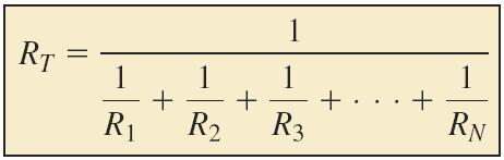
44 PARALLEL RESISTORS FIG. 6.3 Parallel combination of resistors.

45 PARALLEL RESISTORS FIG. 6.6 Network to be investigated in Example 6.3.

46 PARALLEL RESISTORS Instrumentation FIG Using an ohmmeter to measure the total resistance of a parallel network.
47 PARALLEL CIRCUITS A parallel circuit can now be established by connecting a supply across a set of parallel resistors as shown in Fig The positive terminal of the supply is directly connected to the top of each resistor, while the negative terminal is connected to the bottom of each resistor. FIG Parallel network.
48 PARALLEL CIRCUITS In general, the voltage is always the same across parallel elements. Therefore, remember that if two elements are in parallel, the voltage across them must be the same. However, if the voltage across two neighboring elements is the same, the two elements may or may not be in parallel.


49 PARALLEL CIRCUITS FIG Replacing the parallel resistors in Fig with the equivalent total resistance. FIG Mechanical analogy for Fig
50 PARALLEL CIRCUITS For single-source parallel networks, the source current (Is) is always equal to the sum of the individual branch currents. FIG Demonstrating the duality that exists between series and parallel circuits.
51 PARALLEL CIRCUITS FIG Parallel network for Example FIG Parallel network for Example 6.13.
52 PARALLEL CIRCUITS FIG Parallel network for Example 6.14.

53 PARALLEL CIRCUITS Instrumentation FIG Measuring the voltages of a parallel dc network.

54 PARALLEL CIRCUITS Instrumentation FIG Measuring the source current of a parallel network.
55 PARALLEL CIRCUITS Instrumentation FIG Measuring the current through resistor R 1.

56 POWER DISTRIBUTION IN A PARALLEL CIRCUIT FIG Power flow in a dc parallel network.
57 POWER DISTRIBUTION IN A PARALLEL CIRCUIT FIG Parallel network for Example 6.15.
58 KIRCHHOFF S CURRENT LAW In the previous chapter, Kirchhoff s voltage law was introduced, providing a very important relationship among the voltages of a closed path. Kirchhoff is also credited with developing the following equally important relationship between the currents of a network, called Kirchhoff s current law (KCL): The algebraic sum of the currents entering and leaving a junction (or region) of a network is zero.
59 KIRCHHOFF S CURRENT LAW FIG Introducing Kirchhoff s current law.
 Demonstrating Kirchhoff s current law; (b) the water")
60 KIRCHHOFF S CURRENT LAW FIG (a) Demonstrating Kirchhoff s current law; (b) the water analogy for the junction in (a).

61 KIRCHHOFF S CURRENT LAW In technology, the term node is commonly used to refer to a junction of two or more branches. FIG Two-node configuration for Example 6.16.

62 KIRCHHOFF S CURRENT LAW FIG Four-node configuration for Example 6.17.
63 KIRCHHOFF S CURRENT LAW FIG Network for Example 6.18.
64 KIRCHHOFF S CURRENT LAW FIG Parallel network for Example 6.19.

65 KIRCHHOFF S CURRENT LAW FIG Redrawn network in Fig FIG Integrated circuit for Example 6.20.
66 CURRENT DIVIDER RULE For series circuits we have the powerful voltage divider rule for finding the voltage across a resistor in a series circuit. We now introduce the equally powerful current divider rule (CDR) for finding the current through a resistor in a parallel circuit.
67 CURRENT DIVIDER RULE In general: For two parallel elements of equal value, the current will divide equally. For parallel elements with different values, the smaller the resistance, the greater is the share of input current. For parallel elements of different values, the current will split with a ratio equal to the inverse of their resistance values.
68 CURRENT DIVIDER RULE FIG Discussing the manner in which the current will split between three parallel branches of different resistive value. FIG Parallel network for Example 6.21.
69 CURRENT DIVIDER RULE FIG Using the current divider rule to calculate current I1 in Example 6.22.
70 CURRENT DIVIDER RULE Special Case: Two Parallel Resistors FIG Deriving the current divider rule for the special case of only two parallel resistors.
71 CURRENT DIVIDER RULE Special Case: Two Parallel Resistors FIG Using the current divider rule to determine current I 2 in Example FIG A design-type problem for two parallel resistors (Example 6.24).

72 VOLTAGE SOURCES IN PARALLEL FIG Demonstrating the effect of placing two ideal supplies of the same voltage in parallel.

73 OPEN AND SHORT CIRCUITS FIG Defining a short circuit. FIG Defining an open circuit.
74 OPEN AND SHORT CIRCUITS FIG Examples of open circuits.
75 OPEN AND SHORT CIRCUITS FIG Examples of short circuits.
76 OPEN AND SHORT CIRCUITS FIG Networks for Example 6.27.
77 OPEN AND SHORT CIRCUITS FIG Solutions to Example 6.27.
78 OPEN AND SHORT CIRCUITS FIG Network for Example FIG Network in Fig with R 2 replaced by a jumper.

79 SUMMARY TABLE TABLE 6.1 Summary table.
80 Series-Parallel Circuits
81 INTRODUCTION A series-parallel configuration is one that is formed by a combination of series and parallel elements. A complex configuration is one in which none of the elements are in series or parallel.

82 SERIES-PARALLEL NETWORKS FIG. 7.1 Series-parallel dc network.
83 REDUCE AND RETURN APPROACH FIG. 7.3 Series-parallel network for Example 7.1. FIG. 7.4 Substituting the parallel equivalent resistance for resistors R 2 and R 3 in Fig. 7.3.
84 REDUCE AND RETURN APPROACH FIG. 7.5 Series-parallel network for Example 7.2. FIG. 7.6 Schematic representation of the network in Fig. 7.5 after substituting the equivalent resistance R for the parallel combination of R 2 and R 3.

85 REDUCE AND RETURN APPROACH FIG. 7.7 Inserting an ammeter and a voltmeter to measure I 4 and V 2, respectively.
86 BLOCK DIAGRAM APPROACH Once the grouping of elements reveals the most direct approach, you can examine the impact of the individual components in each group. This grouping of elements is called the block diagram approach


87 BLOCK DIAGRAM APPROACH FIG. 7.8 Introducing the block diagram approach. FIG. 7.9 Block diagram format of Fig. 7.3.

88 BLOCK DIAGRAM APPROACH FIG Example 7.3. FIG Reduced equivalent of Fig

89 BLOCK DIAGRAM APPROACH FIG Example 7.4.
90 BLOCK DIAGRAM APPROACH FIG Reduced equivalent of Fig

91 APPLICATIONS Boosting a Car Battery FIG Boosting a car battery.
92 APPLICATIONS Electronic Circuits The operation of most electronic systems requires a distribution of dc voltages throughout the design. Although a full explanation of why the dc level is required (since it is an ac signal to be amplified) will have to wait for the introductory courses in electronic circuits, the dc analysis will proceed in much the same manner as described in this chapter.
93 APPLICATIONS Electronic Circuits FIG The dc bias levels of a transistor amplifier.
94
ชาว ศวกรรมคอมพ วเตอร คณะว ศวกรรมศาสตร มหาว ทยาล ยเทคโนโลย ราชมงคลพระนคร
 EN2042102 วงจรไฟฟ าและอ เล กทรอน กส Circuits and Electronics บทท 5 สารก งต วน า Semiconductor สาขาว ชาว ศวกรรมคอมพ วเตอร คณะว ศวกรรมศาสตร มหาว ทยาล ยเทคโนโลย ราชมงคลพระนคร Bohr model of an atom As seen
ชาว ศวกรรมคอมพ วเตอร คณะว ศวกรรมศาสตร มหาว ทยาล ยเทคโนโลย ราชมงคลพระนคร
 EN2042102 วงจรไฟฟ าและอ เล กทรอน กส Circuits and Electronics บทท 7 ทรานซ สเตอร Bipolar Junction Transistor สาขาว ชาว ศวกรรมคอมพ วเตอร คณะว ศวกรรมศาสตร มหาว ทยาล ยเทคโนโลย ราชมงคลพระนคร Objectives Describe
ชาว ศวกรรมคอมพ วเตอร คณะว ศวกรรมศาสตร มหาว ทยาล ยเทคโนโลย ราชมงคลพระนคร
 EN2042102 วงจรไฟฟ าและอ เล กทรอน กส Circuits and Electronics บทท 6 ไดโอด Diode สาขาว ชาว ศวกรรมคอมพ วเตอร คณะว ศวกรรมศาสตร มหาว ทยาล ยเทคโนโลย ราชมงคลพระนคร Objectives Explain and analyze the operation
EE301 - SERIES CIRCUITS, KIRCHHOFF S VOLTAGE LAW
 Learning Objectives a. Identify elements that are connected in series b. State and apply KVL in analysis of a series circuit c. Determine the net effect of series-aiding and series-opposing voltage sources
Objective of the Lecture
 Objective of the Lecture Present Kirchhoff s Current and Voltage Laws. Chapter 5.6 and Chapter 6.3 Principles of Electric Circuits Chapter4.6 and Chapter 5.5 Electronics Fundamentals or Electric Circuit
10Vdc. Figure 1. Schematics for verifying Kirchhoff's Laws
 ECE 231 Laboratory Exercise 2 Laboratory Group (Names) OBJECTVE Verify Kirchhoff s voltage law Verify Kirchhoff s current law Gain experience in using both an ammeter and voltmeter Construct two (2) circuits
3. Voltage and Current laws
 1 3. Voltage and Current laws 3.1 Node, Branches, and loops A branch represents a single element such as a voltage source or a resistor A node is the point of the connection between two or more elements
Physics 227: Lecture 11 Circuits, KVL, KCL, Meters
 Physics 227: Lecture 11 Circuits, KVL, KCL, Meters Lecture 10 review: EMF ξ is not a voltage V, but OK for now. Physical emf source has V ab = ξ - Ir internal. Power in a circuit element is P = IV. For
Series-Parallel Circuits
 Series-Parallel Circuits INTRODUCTION A series-parallel configuration is one that is formed by a combination of series and parallel elements. A complex configuration is one in which none of the elements
Combined Series and Parallel Circuits
 Combined Series and Parallel Circuits Objectives: 1. Calculate the equivalent resistance, current, and voltage of series and parallel circuits. 2. Calculate the equivalent resistance of circuits combining
OHM'S LAW AND RESISTANCE NETWORKS OBJECT
 17 E7 E7.1 OHM'S LAW AND RESISTANCE NETWORKS OBJECT The objects of this experiment are to determine the voltage-current relationship for a resistor and to verify the series and parallel resistance formulae.
EE215 FUNDAMENTALS OF ELECTRICAL ENGINEERING
 EE215 FUNDAMENTALS OF ELECTRICAL ENGINEERING Tai-Chang Chen University of Washington, Bothell Spring 2010 EE215 1 1 WEEK 2 SIMPLE RESISTIVE CIRCUITS April 9 th, 2010 TC Chen UWB 2010 EE215 2 2 QUESTIONS
Kirchhoff s laws. Objectives. Assessment. Assessment. Assessment. Assessment 5/27/14. Apply Kirchhoff s first and second laws.
 Kirchhoff s laws Objectives Apply Kirchhoff s first and second laws. Calculate the current and voltage for resistor circuits connected in parallel. Calculate the current and voltage for resistor circuits
Laboratory 2 (drawn from lab text by Alciatore)
") Laboratory 2 (drawn from lab text by Alciatore) Instrument Familiarization and Basic Electrical Relations Required Components: 2 1k resistors 2 1M resistors 1 2k resistor Objectives This exercise is designed
Laboratory 2 (drawn from lab text by Alciatore) Instrument Familiarization and Basic Electrical Relations Required Components: 2 1k resistors 2 1M resistors 1 2k resistor Objectives This exercise is designed
Announcements. To stop blowing fuses in the lab, note how the breadboards are wired. EECS 42, Spring 2005 Week 3a 1
 Announcements New topics: Mesh (loop) method of circuit analysis Superposition method of circuit analysis Equivalent circuit idea (Thevenin, Norton) Maximum power transfer from a circuit to a load To stop
Electrical Circuits I (ENGR 2405) Chapter 2 Ohm s Law, KCL, KVL, Resistors in Series/Parallel
 Chapter 2 Ohm s Law, KCL, KVL, Resistors in Series/Parallel") Electrical Circuits I (ENG 2405) Chapter 2 Ohm s Law, KCL, KVL, esistors in Series/Parallel esistivity Materials tend to resist the flow of electricity through them. This property is called resistance
Electrical Circuits I (ENG 2405) Chapter 2 Ohm s Law, KCL, KVL, esistors in Series/Parallel esistivity Materials tend to resist the flow of electricity through them. This property is called resistance
Circuitry II. Name: Date: Section C D F. Mr. Alex Rawson Physics
 Name: Date: Section C D F Circuitry II Mr. Alex Rawson Physics 1. Three resistors of 100, 140, and 80 are placed in a series circuit. a. Find the equivalent resistance. (Your answer should be between 0
Fundamentals of Electric Circuits Chapter 2. Copyright The McGraw-Hill Companies, Inc. Permission required for reproduction or display.
 Fundamentals of Electric Circuits Chapter 2 Copyright The McGraw-Hill Companies, Inc. Permission required for reproduction or display. Overview This chapter will introduce Ohm s law: a central concept
Announcements. To stop blowing fuses in the lab, note how the breadboards are wired. EECS 42, Spring 2005 Week 3a 1
 Announcements New topics: Mesh (loop) method of circuit analysis Superposition method of circuit analysis Equivalent circuit idea (Thevenin, Norton) Maximum power transfer from a circuit to a load To stop
Pre-Lab for Batteries and Bulbs
 Pre-Lab for Batteries and Bulbs Complex circuits composed of resistors can be simplified by using the concept of equivalent resistors. For example if resistors R 1, R 2, and R 3 are connected in series,
Unit-1(A) Circuit Analysis Techniques
 Circuit Analysis Techniques") Unit-1(A Circuit Analysis Techniques Basic Terms used in a Circuit 1. Node :- It is a point in a circuit where two or more circuit elements are connected together. 2. Branch :- It is that part of a network
Unit-1(A Circuit Analysis Techniques Basic Terms used in a Circuit 1. Node :- It is a point in a circuit where two or more circuit elements are connected together. 2. Branch :- It is that part of a network
I. Objectives Upon completion of this experiment, the student should be able to: Ohm s Law
 EENG-201 Experiment # 1 Series Circuit and Parallel Circuits I. Objectives Upon completion of this experiment, the student should be able to: 1. ead and use the resistor color code. 2. Use the digital
PH213 Chapter 26 solutions
 PH213 Chapter 26 solutions 26.6. IDENTIFY: The potential drop is the same across the resistors in parallel, and the current into the parallel combination is the same as the current through the 45.0-Ω resistor.
Unit 8 Combination Circuits
 Unit 8 Combination Circuits Objectives: Define a combination circuit. List the rules for parallel circuits. List the rules for series circuits. Solve for combination circuit values. Characteristics There
Lab 5 Kirchhoff s Laws and Superposition
 Lab 5 Kirchhoff s Laws and Superposition In this lab, Kirchhoff s laws will be investigated using a more complex circuit than in the previous labs. Two voltage sources and seven resistors are included
Laboratory 2. Lab 2. Instrument Familiarization and Basic Electrical Relations. Required Components: 2 1k resistors 2 1M resistors 1 2k resistor
 Laboratory 2 nstrument Familiarization and Basic Electrical Relations Required Components: 2 1k resistors 2 1M resistors 1 2k resistor 2.1 Objectives This exercise is designed to acquaint you with the
Charge Current Voltage
 ECE110 Introduction to Electronics What is? Charge Current Voltage 1 Kirchhoff s Current Law Current in = Current out Conservation of charge! (What goes in must come out, or the total coming in is zero)
Combined Series and Parallel Circuits
 Combined Series and Parallel Circuits Objectives: 1. Calculate the equivalent resistance, current, and voltage of series and parallel l circuits. it 2. Calculate the equivalent resistance of circuits combining
Chapter Two "Bipolar Transistor Circuits"
 Chapter Two "Bipolar Transistor Circuits" 1.TRANSISTOR CONSTRUCTION:- The transistor is a three-layer semiconductor device consisting of either two n- and one p-type layers of material or two p- and one
Prelab 4 Millman s and Reciprocity Theorems
 Prelab 4 Millman s and Reciprocity Theorems I. For the circuit in figure (4-7a) and figure (4-7b) : a) Calculate : - The voltage across the terminals A- B with the 1kΩ resistor connected. - The current
Solution: Based on the slope of q(t): 20 A for 0 t 1 s dt = 0 for 3 t 4 s. 20 A for 4 t 5 s 0 for t 5 s 20 C. t (s) 20 C. i (A) Fig. P1.
: 20 A for 0 t 1 s dt = 0 for 3 t 4 s. 20 A for 4 t 5 s 0 for t 5 s 20 C. t (s) 20 C. i (A) Fig. P1.") Problem 1.24 The plot in Fig. P1.24 displays the cumulative charge q(t) that has entered a certain device up to time t. Sketch a plot of the corresponding current i(t). q 20 C 0 1 2 3 4 5 t (s) 20 C Figure
Problem 1.24 The plot in Fig. P1.24 displays the cumulative charge q(t) that has entered a certain device up to time t. Sketch a plot of the corresponding current i(t). q 20 C 0 1 2 3 4 5 t (s) 20 C Figure
Ohm s and Kirchhoff s Circuit Laws. Abstract. Introduction and Theory. EE 101 Spring 2006 Date: Lab Section #: Lab #2
 EE 101 Spring 2006 Date: Lab Section #: Lab #2 Name: Ohm s and Kirchhoff s Circuit Laws Abstract Rev. 20051222JPB Partner: Electrical circuits can be described with mathematical expressions. In fact, it
ECE 53A: Fundamentals of Electrical Engineering I
 ECE 53A: Fundamentals of Electrical Engineering I Laboratory Assignment #1: Instrument Operation, Basic Resistor Measurements and Kirchhoff s Laws Fall 2007 General Guidelines: - Record data and observations
AP Physics - Problem Drill 14: Electric Circuits
 AP Physics - Problem Drill 14: Electric Circuits No. 1 of 10 1. Identify the four electric circuit symbols. (A) 1. AC power 2. Battery 3. Light Bulb 4. Resistor (B) 1. Ammeter 2. Resistor 3. AC Power 4.
ENGR 1181 Lab 3: Circuits
 ENGR 1181 Lab 3: Circuits - - Lab Procedure - Report Guidelines 2 Overview of Circuits Lab: The Circuits Lab introduces basic concepts of electric circuits such as series and parallel circuit, used in
electronics fundamentals
 electronics fundamentals circuits, devices, and applications THOMAS L. FLOYD DAVID M. BUCHLA chapter 6 Identifying series-parallel relationships Most practical circuits have combinations of series and
Direct Current Circuits
 PC1143 Physics III Direct Current Circuits 1 Objectives Apply Kirchhoff s rules to several circuits, solve for the currents in the circuits and compare the theoretical values predicted by Kirchhoff s rule
PHYS 1112L - Introductory Physics Laboratory II
 PHYS 1112L - Introductory Physics Laboratory II Laboratory Advanced Sheet dc Circuits 1. Objectives. The objectives of this laboratory are a. to be able to construct dc circuits given a circuit diagram
Experiment #3: Experimenting with Resistor Circuits
 Name/NetID: Experiment #3: Experimenting with Resistor Circuits Laboratory Outline During the semester, the lecture will provide some of the mathematical underpinnings of circuit theory. The laboratory
Chapter Three " BJT Small-Signal Analysis "
 Chapter Three " BJT Small-Signal Analysis " We now begin to examine the small-signal ac response of the BJT amplifier by reviewing the models most frequently used to represent the transistor in the sinusoidal
Lab 3 DC CIRCUITS AND OHM'S LAW
 43 Name Date Partners Lab 3 DC CIRCUITS AND OHM'S LAW AMPS + - VOLTS OBJECTIVES To learn to apply the concept of potential difference (voltage) to explain the action of a battery in a circuit. To understand
EET140/3 ELECTRIC CIRCUIT I
 SCHOOL OF ELECTRICAL SYSTEM ENGINEERING UNIVERSITI MALAYSIA PERLIS EET140/3 ELECTRIC CIRCUIT I MODULE 1 PART I: INTRODUCTION TO BASIC LABORATORY EQUIPMENT PART II: OHM S LAW PART III: SERIES PARALEL CIRCUIT
Experiment #3 Kirchhoff's Laws
 SAN FRANCSC STATE UNVERSTY ELECTRCAL ENGNEERNG Kirchhoff's Laws bjective To verify experimentally Kirchhoff's voltage and current laws as well as the principles of voltage and current division. ntroduction
Source Transformations
 Source Transformations Introduction The circuits in this set of problems consist of independent sources, resistors and a meter. In particular, these circuits do not contain dependent sources. Each of these
DC CIRCUITS AND OHM'S LAW
 July 15, 2008 DC Circuits and Ohm s Law 1 Name Date Partners DC CIRCUITS AND OHM'S LAW AMPS - VOLTS OBJECTIVES OVERVIEW To learn to apply the concept of potential difference (voltage) to explain the action
BJT AC Analysis CHAPTER OBJECTIVES 5.1 INTRODUCTION 5.2 AMPLIFICATION IN THE AC DOMAIN
 BJT AC Analysis 5 CHAPTER OBJECTIVES Become familiar with the, hybrid, and hybrid p models for the BJT transistor. Learn to use the equivalent model to find the important ac parameters for an amplifier.
DC/AC CIRCUITS: CONVENTIONAL FLOW TEXTBOOKS
 4 PEARSON CUSTOM ELECTRONICS TECHNOLOGY DC/AC CIRCUITS: CONVENTIONAL FLOW TEXTBOOKS AVAILABLE MARCH 2009 Boylestad Introductory Circuit Analysis, 11/e, 0-13-173044-4 Introduction 32 LC4501 Voltage and
Lab #1: Electrical Measurements I Resistance
 Lab #: Electrical Measurements I esistance Goal: Learn to measure basic electrical quantities; study the effect of measurement apparatus on the quantities being measured by investigating the internal resistances
Chapter 8. Constant Current Sources
 Chapter 8 Methods of Analysis Constant Current Sources Maintains same current in branch of circuit Doesn t matter how components are connected external to the source Direction of current source indicates
Real Analog Chapter 2: Circuit Reduction. 2 Introduction and Chapter Objectives. After Completing this Chapter, You Should be Able to:
 1300 Henley Court Pullman, WA 99163 509.334.6306 www.store. digilent.com 2 Introduction and Chapter Objectives In Chapter 1, we presented Kirchhoff's laws (which govern the interaction between circuit
Series and parallel resistances
 Series and parallel resistances Objectives Calculate the equivalent resistance for resistors connected in both series and parallel combinations. Construct series and parallel circuits of lamps (resistors).
Oregon State University Lab Session #1 (Week 3)
") Oregon State University Lab Session #1 (Week 3) ENGR 201 Electrical Fundamentals I Equipment and Resistance Winter 2016 EXPERIMENTAL LAB #1 INTRO TO EQUIPMENT & OHM S LAW This set of laboratory experiments
Oregon State University Lab Session #1 (Week 3) ENGR 201 Electrical Fundamentals I Equipment and Resistance Winter 2016 EXPERIMENTAL LAB #1 INTRO TO EQUIPMENT & OHM S LAW This set of laboratory experiments
Paper-1 (Circuit Analysis) UNIT-I
 UNIT-I") Paper-1 (Circuit Analysis) UNIT-I AC Fundamentals & Kirchhoff s Current and Voltage Laws 1. Explain how a sinusoidal signal can be generated and give the significance of each term in the equation? 2. Define
Paper-1 (Circuit Analysis) UNIT-I AC Fundamentals & Kirchhoff s Current and Voltage Laws 1. Explain how a sinusoidal signal can be generated and give the significance of each term in the equation? 2. Define
Designing Information Devices and Systems I Spring 2019 Lecture Notes Note Introduction to Electrical Circuit Analysis
 EECS 16A Designing Information Devices and Systems I Spring 2019 Lecture Notes Note 11 11.1 Introduction to Electrical Circuit Analysis Our ultimate goal is to design systems that solve people s problems.
Solving Series Circuits and Kirchhoff s Voltage Law
 Exercise 6 Solving Series Circuits and Kirchhoff s Voltage Law EXERCISE OBJECTIVE When you have completed this exercise, you will be able to calculate the equivalent resistance of multiple resistors in
Chapter 23 Circuits. Chapter Goal: To understand the fundamental physical principles that govern electric circuits. Slide 23-1
 Chapter 23 Circuits Chapter Goal: To understand the fundamental physical principles that govern electric circuits. Slide 23-1 Chapter 23 Preview Looking Ahead: Analyzing Circuits Practical circuits consist
Physics 201 Laboratory: Analog and Digital Electronics. I-0. Introductory Notes
 Physics 201 Laboratory: Analog and Digital Electronics -0. ntroductory Notes Definitions of circuit and current. Current is the flow of charge. We may think of electrons flowing through a wire as a current
+ R 2. EE 2205 Lab 2. Circuit calculations: Node-Voltage and Mesh-Current
 Circuit calculations: Node-Voltage and Mesh-Current We continue our study of some simple and representative circuits as we develop and practice our understanding of basic circuit analysis techniques. Below
Survival Skills for Circuit Analysis
 P. R. Nelson Fall 2010 WhatToKnow - p. 1/46 Survival Skills for Circuit Analysis What you need to know from ECE 109 Phyllis R. Nelson prnelson@csupomona.edu Professor, Department of Electrical and Computer
CHAPTER 9. Sinusoidal Steady-State Analysis
 CHAPTER 9 Sinusoidal Steady-State Analysis 9.1 The Sinusoidal Source A sinusoidal voltage source (independent or dependent) produces a voltage that varies sinusoidally with time. A sinusoidal current source
Solving Parallel and Mixed Circuits, and Kirchhoff s Current Law
 Exercise 7 Solving Parallel and Mixed Circuits, and Kirchhoff s Current Law EXERCISE OBJECTIVE When you have completed this exercise, you will be able to calculate the equivalent resistance of multiple
Lecture # 4 Network Analysis
 CPEN 206 Linear Circuits Lecture # 4 Network Analysis Dr. Godfrey A. Mills Email: gmills@ug.edu.gh Phone: 026-907-3163 February 22, 2016 Course TA David S. Tamakloe 1 What is Network Technique o Network
Lab Experiment No. 4
 Lab Experiment No. Kirchhoff s Laws I. Introduction In this lab exercise, you will learn how to read schematic diagrams of electronic networks, how to draw and use network graphs, how to transform schematics
ES250: Electrical Science. HW6: The Operational Amplifier
 ES250: Electrical Science HW6: The Operational Amplifier Introduction This chapter introduces the operational amplifier or op amp We will learn how to analyze and design circuits that contain op amps,
UNIT 4 BIASING AND STABILIZATION
 UNIT 4 BIASING AND STABILIZATION TRANSISTOR BIASING: To operate the transistor in the desired region, we have to apply external dec voltages of correct polarity and magnitude to the two junctions of the
Electric Circuits I. Simple Resistive Circuit. Dr. Firas Obeidat
 Electric Circuits I Simple Resistive Circuit Dr. Firas Obeidat 1 Resistors in Series The equivalent resistance of any number of resistors connected in series is the sum of the individual resistances. It
Electric Circuits. Physics 6 th Six Weeks
 Electric Circuits Physics 6 th Six Weeks Electric Circuits (a review) A circuit is a path through which electricity can flow Electric Circuits always contain 3 things: a voltage source, a conductor (usually
Lecture Week 5. Quiz #2 Ohm s Law Homework Power Review Shorthand Notation Active Components Ideal Op-amps
 Lecture Week 5 Quiz #2 Ohm s Law Homework Power Review Shorthand Notation Active Components Ideal Op-amps Quiz 2 Ohm s Law (20 pts.) Please clear desks and turn off phones and put them in back packs You
Engineering Laboratory Exercises (Electric Circuits Module) Prepared by
 Prepared by") Engineering 1040 Laboratory Exercises (Electric Circuits Module) Prepared by Eric W. Gill FALL 2008 2 EXP 1040-EL1 VOLTAGE, CURRENT, RESISTANCE AND POWER PURPOSE To (i) investigate the relationship between
Engineering 1040 Laboratory Exercises (Electric Circuits Module) Prepared by Eric W. Gill FALL 2008 2 EXP 1040-EL1 VOLTAGE, CURRENT, RESISTANCE AND POWER PURPOSE To (i) investigate the relationship between
3.4 The Single-Loop Circuit Single-loop circuits
 25 3.4 The Single-Loop Circuit Single-loop circuits Elements are connected in series All elements carry the same current We shall determine The current through each element The voltage across each element
Circuits. Ch. 35 in your text book
 Circuits Ch. 35 in your text book Objectives Students will be able to: 1) Draw schematic symbols for electrical circuit components 2) Calculate the equivalent resistance for a series circuit 3) Calculate
Closed circuit complete path for electrons follow. Open circuit no charge flow and no current.
 Section 1 Schematic Diagrams and Circuits Electric Circuits, continued Closed circuit complete path for electrons follow. Open circuit no charge flow and no current. short circuit closed circuit, no load.
DC Bias. Graphical Analysis. Script
 Course: B.Sc. Applied Physical Science (Computer Science) Year & Sem.: Ist Year, Sem - IInd Subject: Electronics Paper No.: V Paper Title: Analog Circuits Lecture No.: 3 Lecture Title: Analog Circuits
SCHEMATIC OF GRAYMARK 808 POWERED BREADBOARD
 SCHEMATIC OF GRAYMARK 808 POWERED BREADBOARD 1a white SW1 white 2a TP1 blue TP2 black blue TP3 TP4 yellow TP5 yellow TP6 4 3 8 7 + D1 D2 D5 D6 C1 R1 TP8 Q1 R3 TP12 2 TP18 U2-0-15V C8 9 C2 + TP15 C5 R12
hing/fall16/electric_circuits.html
 http://sist.shanghaitech.edu.cn/faculty/zhoupq/teac hing/fall16/electric_circuits.html Circuit Terminology & Kirchhoff s Laws 9/14/2016 Reading: Chapter 1&2&3 2 Outline Circuit Terminology Charge, Current,
Transistor Biasing. DC Biasing of BJT. Transistor Biasing. Transistor Biasing 11/23/2018
 Transistor Biasing DC Biasing of BJT Satish Chandra Assistant Professor Department of Physics P P N College, Kanpur www.satish0402.weebly.com A transistors steady state of operation depends a great deal
V (in volts) = voltage applied to the circuit, I (in amperes) = current flowing in the circuit, R (in ohms) = resistance of the circuit.
 = voltage applied to the circuit, I (in amperes) = current flowing in the circuit, R (in ohms) = resistance of the circuit.") OHM S LW OBJECTIES: PRT : 1) Become familiar with the use of ammeters and voltmeters to measure DC voltage and current. 2) Learn to use wires and a breadboard to build circuits from a circuit diagram.
OHM S LW OBJECTIES: PRT : 1) Become familiar with the use of ammeters and voltmeters to measure DC voltage and current. 2) Learn to use wires and a breadboard to build circuits from a circuit diagram.
CK-12 Physics Concepts - Intermediate Answer Key
 Chapter 19: Electrical Circuits 19.1 Series Circuits CK-12 Physics Concepts - Intermediate Answer Key 1. There are three 20.0 Ohm resistors connected in series across a 120 V generator. a. What is the
Experiment 8: Semiconductor Devices
 Name/NetID: Experiment 8: Semiconductor Devices Laboratory Outline In today s experiment you will be learning to use the basic building blocks that drove the ability to miniaturize circuits to the point
This is a limited subset of the types and difficulties of the questions from the 2013 State Competition.
 This is a limited subset of the types and difficulties of the questions from the 2013 State Competition. It is NOT meant to be all inclusive or complete, or to limit the scope of the 2014 competition in
In this lecture, we will learn about some more basic laws governing the behaviour of electronic circuits beyond that of Ohm s law.
 In this lecture, we will learn about some more basic laws governing the behaviour of electronic circuits beyond that of Ohm s law. 1 Consider this circuit here. There is a voltage source providing power
fiziks Institute for NET/JRF, GATE, IIT-JAM, M.Sc. Entrance, JEST, TIFR and GRE in Physics
 nstitute for NT/JF, GAT, T-JAM, M.Sc. ntrance, JST, TF and G in Physics 3. ipolar Junction Transistors 3.1 Transistor onstruction Transistor is a three-layer semiconductor device consisting of either two
Experiment 3. Ohm s Law. Become familiar with the use of a digital voltmeter and a digital ammeter to measure DC voltage and current.
 Experiment 3 Ohm s Law 3.1 Objectives Become familiar with the use of a digital voltmeter and a digital ammeter to measure DC voltage and current. Construct a circuit using resistors, wires and a breadboard
Experiment 2. Ohm s Law. Become familiar with the use of a digital voltmeter and a digital ammeter to measure DC voltage and current.
 Experiment 2 Ohm s Law 2.1 Objectives Become familiar with the use of a digital voltmeter and a digital ammeter to measure DC voltage and current. Construct a circuit using resistors, wires and a breadboard
EK307 Introduction to the Lab
 EK307 Introduction to the Lab Learning to Use the Test Equipment Laboratory Goal: Become familiar with the test equipment in the electronics laboratory (PHO105). Learning Objectives: Voltage source and
Homework Assignment 06
 Homework Assignment 06 Question 1 (Short Takes) One point each unless otherwise indicated. 1. Consider the current mirror below, and neglect base currents. What is? Answer: 2. In the current mirrors below,
EEE 2101 Circuit Theory I - Laboratory 1 Kirchoff s Laws, Series-Parallel Circuits
 ame & Surname: D: Date: EEE 20 Circuit Theory - Laboratory Kirchoff s Laws, Series-Parallel Circuits List of topics for this laboratory: Ohm s Law Kirchoff s Current Law(KCL) Kirchoff s Voltage Law(KVL)
Exam Below are two schematics of current sources implemented with MOSFETs. Which current source has the best compliance voltage?
 Exam 2 Name: Score /90 Question 1 Short Takes 1 point each unless noted otherwise. 1. Below are two schematics of current sources implemented with MOSFETs. Which current source has the best compliance
Electric Circuit Analysis Using Voltage Maps and PSpice { TC \l1 "} Introduction{ TC \l3 "}
 Electric Circuit Analysis Using Voltage Maps and PSpice { TC \l1 "} Russell E. Puckett, PE, Professor Emeritus Texas A&M University, College Station, TX 77843 { TC \l2 "} Abstract Engineering students
Chapter 26: Direct current circuit
 Chapter 26: Direct current circuit Resistors in circuits Equivalent resistance The nature of the electric potential and current in circuit Kirchhoff s rules (for complicated circuit analysis) Resistors
Lab 3: Kirchhoff's Laws and Basic Instrumentation
 Lab 3: Kirchhoff's Laws and Basic Instrumentation By: Gary A. Ybarra Christopher E. Cramer Duke Universty Department of Electrical and Computer Engineering Durham, NC 1. Purpose The purpose of this exercise
ELT 215 Operational Amplifiers (LECTURE) Chapter 5
 Chapter 5") CHAPTER 5 Nonlinear Signal Processing Circuits INTRODUCTION ELT 215 Operational Amplifiers (LECTURE) In this chapter, we shall present several nonlinear circuits using op-amps, which include those situations
CHAPTER 5 Nonlinear Signal Processing Circuits INTRODUCTION ELT 215 Operational Amplifiers (LECTURE) In this chapter, we shall present several nonlinear circuits using op-amps, which include those situations
Component modeling. Resources and methods for learning about these subjects (list a few here, in preparation for your research):
:") Component modeling This worksheet and all related files are licensed under the Creative Commons Attribution License, version 1.0. To view a copy of this license, visit http://creativecommons.org/licenses/by/1.0/,
Component modeling This worksheet and all related files are licensed under the Creative Commons Attribution License, version 1.0. To view a copy of this license, visit http://creativecommons.org/licenses/by/1.0/,
30V 30 R1 120V R V 30 R1 120V. Analysis of a single-loop circuit using the KVL method
 Analysis of a singleloop circuit using the KVL method Below is our circuit to analyze. We shall attempt to determine the current through each element, the voltage across each element, and the power delivered
SCRIPT. Voltage Dividers
 SCRIPT Hello friends in our earlier discussion we talked about series resistive circuits, when connected in series, resistors form a "string" in which there is only one path for current. Ohm's law can
Chapter two. Basic Laws. 2.1 Introduction
 2.1 Introduction Chapter two Basic Laws Chapter 1 introduced basic concepts in an electric circuit. To actually determine the values of these variables in a given circuit requires that we understand some
Regents Physics Mr. Mellon Based on Chapter 22 and 23
 Name Regents Physics Mr. Mellon Based on Chapter 22 and 23 Essential Questions What is current? How is it measured? What are the relationships for Ohm s Law? What device measures current and how is it
Electrical Measurements
 Electrical Measurements. OBJECTIES: This experiment covers electrical measurements, including use of the volt-ohmmeter and oscilloscope. Concepts including Ohm's Law, Kirchoff's Current and oltage Laws,
Real Analog Chapter 3: Nodal & Mesh Analysis. 3 Introduction and Chapter Objectives. 3.1 Introduction and Terminology
 Real Analog Chapter 3: Nodal & Mesh Analysis 1300 Henley Court Pullman, WA 99163 509.334.6306 www.store.digilent.com 3 Introduction and Chapter Objectives In Chapters 1 & 2, we introduced several tools
Lab 4 OHM S LAW AND KIRCHHOFF S CIRCUIT RULES
 57 Name Date Partners Lab 4 OHM S LAW AND KIRCHHOFF S CIRCUIT RULES AMPS - VOLTS OBJECTIVES To learn to apply the concept of potential difference (voltage) to explain the action of a battery in a circuit.